Aaaand, we’re back!

Surprise! Doubtless you thought the truck had been sold or I’ve given up on the project. Actually, not; but there is so much to catch you up on that I hardly know where to start. The short version is that The Green Truck blog now has a basis for reanimation, though probably the restart will be not nearly as active as when it was started.

Over the next few weeks I plan to restart the blog entries–with the caveat that I am also really, really busy with classes and a front yard reset that needs to be completed, plus a couple of time-sensitive wood projects that have to be finished early in the new year. I’ll fit those stories into the story as we go.

I’m glad to be back.

Merely an interruption . . .

My, my—has it really been more than a year since I have posted an entry? I have to admit rather sheepishly that it has, but I have a good excuse—money.

For the last year and a half work on the Green Truck has been on hold while I’ve scrimped and saved up money to get the engine rebuilt. Yes, I had hoped to be able to do the work myself, but I finally had to admit to myself that I lacked the time, the knowledge, and the tools to do so. Three strikes and you’re out. I am afraid that I let The Green Truck lapse from inattention and did not tell anyone why or what I was doing.

In my own defense, while I was at work on the fiscal end of Truck things, I’ve managed to keep myself busy with other projects, like building Dear the rocking chair I’ve been promising for thirty years.

Dear’s cherry rocker

Saving up the four figures required for the machining work to be done on the engine has taken up that year and a half. Finally the money has been gleaned and I am ready to pick up the story again. Start looking for new installments of The Green Truck again, hopefully weekly, but certainly with a shorter frequency than every year and a half.

Pulling the head.

With the manifold off, I’ve reached a point in disassembling the engine that the really big stuff has to be faced.  This step involves removing the head from the block.

2019feb16-07a

Removal of the first bolt, driver’ side front.

There are twenty bolts of varying lengths running along either side, one between each cylinder plus two at either end.  These are torqued to specific pressure so that the head unit is held down evenly across the surface of the block.  Two of the bolts (well, more than two) came out when I installed the lift chain to remove the motor from the chassis, but the rest are ready to come out now.

2019feb16-07b

I’ve set them back in place to keep them in order.

With all the bolts loosened, the head did not simply lift off.  A few good whacks with the dead-blow mallet were required to break the seal between the two parts and the gasket.

2019feb16-07c

As you can see, each of the bolts gets bagged in its group and filed in my growing pile of parts.

The head itself is a casting, with the added weight of sixteen valves and springs.  A cursory examination suggests that the head is in good shape.  I could not see any obvious crack that would require replacing the head, but the head will be checked by the machinist for sure.

2019feb16-08c

The intake and exhaust valves for the sixth cylinder, showing carbon buildup.

As I’ve explored the automotive mysteries I’ve learned that the valve seats in the head will require attention.  They have to be hardened to deal with the temperatures generated by the present mixture of the unleaded gasoline formulated today—a hotter-burning E85 gasoline-ethanol mixture.  That will be part of the job of the machinist; I’ve just got to get everything into their hands.


Oil filter and manifold.

2019feb16-01

I am a long way from rebuilding the carburetor, but it, the oil filter, and manifolds have to come off the block first.

The first matter was to disconnect and remove the accelerator assembly.  This is the business end of the gas pedal, translating the action of your foot into a series of actions controlling the fuel mixture into the engine.  You can see that there are various springs, rods, and pivots that had to be disassembled. Those are the images above.  Below, the oil filter is shown in place, before removal.  In the image beside it, the ports are shown in the block.  The oil filter is mounted to the manifold by a pair of U-bolts.  It was simplicity to unbolt and remove them, not even worth an image to prove I did it.

The carburetor was unmounted from the manifold body

It was a little more work to get the intake and exhaust manifolds disconnected. There was no way to get the impact wrench into the space between the manifold and the block, so the only option was a combination wrench.  Frankly, though nothing has moved since the motor was rebuilt who knows how long ago, the bolts were not a problem.


A few twists with the wrench, and off came the intake and exhaust manifolds as a single unit.  I won’t take those apart because a machinist will have to grind the faces smooth in machining.

2019feb16-05c

Being able to turn the manifold around in my hands revealled a couple more casting codes about which I have no idea.  I know that the GM number is not for General Motors but for the Saginaw Metal Castings plant, a component maker for Chevrolet.

and here is the driver’s side of the block with the manifolds removed.  At this point the gasket has not been removed, but it came off with a tug.

2019feb16-06a

So this leaves the block bare on the driver’s side.  The next step takes me right inside the motor.

(By the way, James, she’s terrific. Congratulations.)

Flywheel and clutch housing.

With the clutch removed, the process of getting off the clutch housing proved to be involved enough that I will make it yet another separate post.  Truthfully, removing the starter, clutch, flywheel, and clutch housing, and then mounting the motor to an engine stand were all accomplished in a single long day, but I need to talk this through and document it for my own benefit as well as either of my readers, so a separate post it is.

2019feb01-10

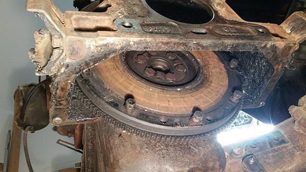
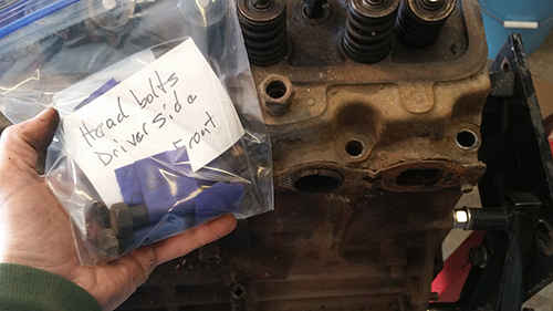
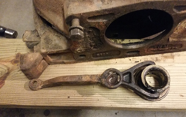
Here (above) is the flywheel in place, with the bolts for the clutch replaced (so I don’t lose them).  Below, the three groups of paired bolts holding the flywheel to the crankshaft are visible.  The metal straps through which they are bolted are anti-unbolting devices.  Each corner of the strap is folded up beside each bolt head, making a tab that keeps the bolt from turning. As you can see below, I used a cold chisel (and should have used a drift punch) to tap the corners/tabs down flat so the bolts can be unscrewed.

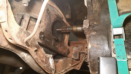
With the mounting bolts removed, the flywheel simply had to be tapped gently from the end of the crankshaft.  There is no room at all inside the clutch housing, so that was most easily accomplished through the hole left by removal of the starter motor.  Fortunately I have a piece of leftover hickory that worked perfectly: some light taps on the hickory, turn the flywheel (and crank), s’more light taps, and eventually the flywheel moved back far enough on the crank that I could pull it manually.

Once loosened, the flywheel simply lifted off and was filed as well.

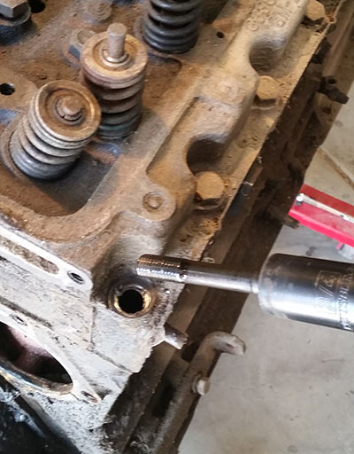
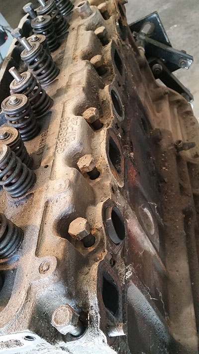
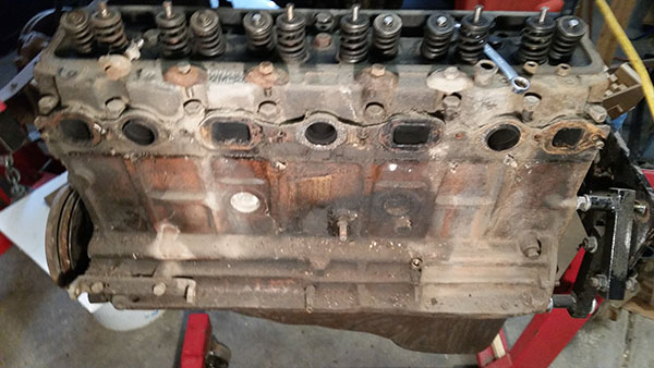
Removing the flywheel finally gave me access to the internal mounting bolts attaching the clutch housing to the engine block.  As you can see, this was not a minor deal.  There are four bolts, and inside the dark recesses of the housing, they were hard to spot beneath the accumulated grease, dust, animal hair, leaves, straw, sticks, etc.  They were easily removed, however.  Remember, the clutch housing is not exactly hermetically sealed.  A few smacks with the hammer loosened the housing and it simply lifted off

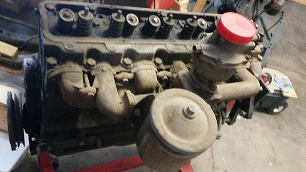
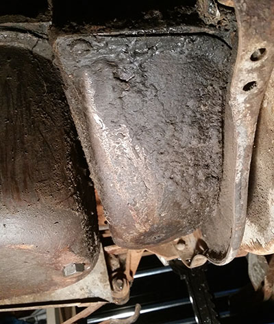
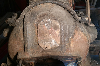
Curiously, the clutch housing has a port at the top, covered by a plate.  On Green the plate had only a single screw, but I think I found the other earlier in the action.  That thing that looks like a handle, running across the top of the housing, is the linkage from the starter pedal to the motor.  Remember, Green is of an age that it has a kick-starter rather than an electric start.  It makes a convenient handle for the chunk of metal that is the housing.  The picture, below, was taken before removing the housing, but you get the message.

2019feb01-12a

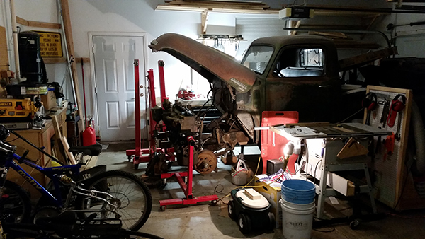
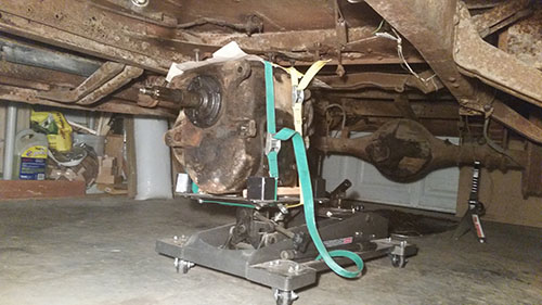
At this point the engine was mounted to the stand as described in the earlier post, and I disassembled the hoist, shoving it to one side.

Now the motor comes apart.


Fuel pump.

Somewhere along the line I missed the detail of removing the fuel pump.  This entry, then, is a belated catch-up.  Already got the story on the fuel line in Step 8.

On most modern vehicles, a fuel pump is an electric motor.  On the Green Truck, the fuel pump is a mechanical pump driven by the camshaft.  Removing it was simple.  A couple of bolts, and it was off.


Looking at the fuel pump more closely off of the engine, I have to think that it may have been installed more recently than 1949.  Probably a replacement.


Starter and clutch.

Now, an inline-6 engine is heavy, to the tune of several hundred pounds of cast and machined steel, but the clutch, flywheel, and clutch housing, which sits between the now-removed transmission and the engine block, adds probably another seventy pounds and has to come off.  The engine cannot be mounted of the engine stand until the clutch housing comes off.  I am backtracking here, because in my previous post I showed you that the clutch housing was removed and the engine is on the stand.  This is that process.

That starter has to come off first.  The starter is an electric motor which spins the flywheel, which turned the pistons and allows the internal combustion cycle to start. The images below show the starter in place on the passenger side of the engine.  Curiously, the lower bolt has been replaced with one too long and shimmed by a stack of washers.


As you can see, it was a simple matter to extract the two mounting bolts and pull off the starter motor.  That gives me a new serial number for my tally sheet.

2019feb01-4

The first thing removed is the clutch fork and throwout bearing.  They simply lifted out with a bit of wiggling through the available space.

2019feb01-5

Once the starter was filed in my growing pile of parts, the clutch assembly has to be dropped.  That involves a dozen bolts around the edge, bolting the clutch to the flywheel.   That requires working from the underside.  I had previously pulled the clutch cover, which amounted to only a couple of bolts.


Here is the assembly, posing on the garage floor (no, I didn’t drop it).


The clutch assembly will likely have to be replaced, but I’ll have someone who knows more than I do tell me whether that is positively so.  I’d like to keep everything original to the truck, but good sense may dictate that Green needs a new essential element.  Discretion, y’know.


And, heave!

With the transmission disconnected and the motor mounts unbolted, it was a simple matter to let the hoist lift the motor off the chassis. I had planned an engine party for various guys I know, but the process of lifting the engine was so simple that I think a party would have been a bigger deal than the action merited.  Frankly, I did it all by myself.  The bottom image shows the motor with the clutch and housing in place.


Getting the motor onto the engine stand was a bit more difficult.  The clutch housing had to come off first, and I will make that a separate post, but mounting the engine to the stand fits here.

As you can see from the image above, I put a loose piece of pressure-treated 2×6 under the back end of the clutch and another length of 2×4 under the front.  Yes, it could have hung there, but lowering the seriously heavy motor onto the wood supports took the weight off the hoist’s ram (hey, I’m borrowing this and need to treat it nicely).

Off came the clutch, flywheel, and clutch housing and then it went back into the air to get in position for the engine stand.  I had bought half-inch grade 8 bolts, but it turns out the bolts holding the clutch housing to the block were 7/16-inch.  It required a couple of trips to the hardware store to match everything up correctly.  I hadn’t noticed that the upright on the stand cants back at an angle, so I needed four bolts all right, but of two different lengths.  The other problem was that the engine stand was built for V-6 and V-8 engines and the movable arms did not match up very well with an old straight-six motor.  I finally unbolted the arms and improvised—all the parts are there, but not in the order intended.  Hey, it works.


So, this is what my crowded little workspace looks like now as I begin tearing down the engine.

2018dec26-11

I think the job is just beginning.

Didn’t see that coming . . .

I followed instructions on removing the engine from the frame and found that the manual fails utterly to take into account that the cab is on the truck and has not half an inch of clearance.  For that reason, I am fairly sure that whoever wrote the manual assumed that the assembly-line steps for installing the motor in the factory could be reversed.  Undoubtedly the motor, clutch, and transmission were dropped onto the chassis already bolted together, so that the manual author simply printed the steps in reverse order.

What the manual author neglected was that the motor-clutch-transmission sits astride an integral chassis frame cross-member, and the cab sits atop that.  That means the motor cannot be removed in the way the manual suggests, because there is no clearance between the top of the clutch-transmission and the bottom of the cab’s foot panel, not nearly enough to lift the clutch-transmission two inches to clear the frame’s cross-member, which is riveted in place.  The transmission has to come off first.

I got the Helpful Neighbor to come look at things and confirm my suspicion.  He did, and later the same afternoon brought over his transmission jack.  Saved me another couple hundred dollars in the process.  The transmission is strapped onto the carriage to keep it from rolling off onto the hapless mechanic—which could deliver a two-hundred pound, possibly fatal steel headache, for sure.

2018dec26-1

The clutch cover, from the driver’s side; oil pan to the left. The immovable frame cross member is on the right.

To get the transmission off required figuring out where the bolts were.  There are two bolts holding together the transmission and the clutch housing.  They came off without a hitch, but nothing moved.  Something else was holding things together from the other side, which meant inside the clutch housing.  The clutch cover was simple to remove–bolt on either side into the clutch housing.  The back side of the cover slides over the top of the frame cross member to close off the clutch.

Inside the clutch housing, there were a couple of bolt heads hidden inside and threaded into the transmission from the opposite direction.  A combination wrench took care of those, since there is not nearly enough room for a socket wrench (but then, the Green Truck was designed before socket wrenches).  With those removed, it was a simple matter to push the transmission straight back.

2018dec26-4

So, the transmission is parked for the time being back by the differential.  I can’t get it out from under the truck at this point, and don’t have anywhere else to store, it anyway.

2018dec26-5

So now let’s get the engine out.

Sadie.

Took a weekend breather from the Green Truck to help Girl 3 with an automotive reality on her first car—a 1995 Honda Accord with a wheezy radiator.  Took her to Napa to get a replacement (which they had in stock) on Friday afternoon and we talked through the basics.

It blew a hurricane Friday night and was still howling on Saturday morning, so we pulled Sadie (every car needs a proper name) into the garage and I set to work teaching her the differences and uses of combination wrenches and sockets.  I did not teach her any words used to emphasize automotive frustration.


As you can see, the Green Truck’s front end is positively roomy compared with the labyrinthine clutter of a modern transverse-engine compartment. There was barely enough room to work.

Yes, I helped, but Girl 3 did most of the work. It took almost all day because she was inexperienced and because we learned that modern vehicles have a transmission cooling line that runs through the radiator.  The flare nut on the intake line was not tightened sufficiently, but we didn’t find out until there was plenty of fluid under the front end as we were running it.  One of the two fans had to be removed so the nut could be tightened, but that took only half an hour’s work and thankfully we did not have to drain the radiator again.

By the end of the day Girl 3 got a car that will now pass inspection and can be licensed.  She also got a tutorial and some hands-on experience in some basic tools and automotive issues.  I got a hug from my once-little girl.

I think dad got the better part of the deal.